Is the line gravity flow?
Sewer, stormwater, drainage and project-reviewed marine outfall enter this system route.
 largeHDPEpipe.com
Start a project ↗
Gravity & structural duty · Core system 01
A steel-wire-reinforced HDPE structured-wall system for sewer, stormwater, drainage and oversized buried infrastructure—selected around flow, stiffness, ground, jointing and logistics.
01 / Project fit check
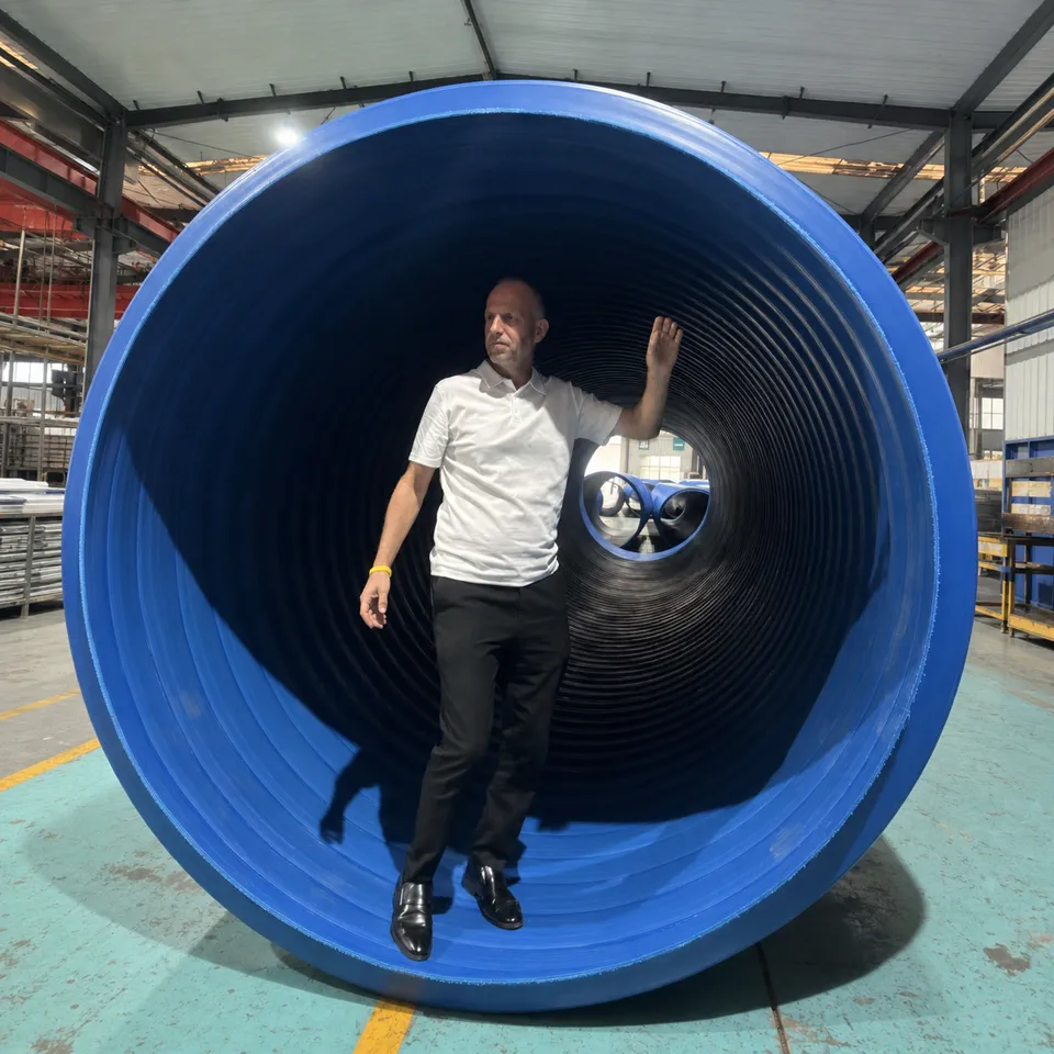
Large-diameter HDPE structured-wall pipe is the gravity-flow route for sewer, stormwater and buried drainage projects. Selection starts with flow and diameter basis, then ring stiffness, burial conditions, jointing, installation quality and logistics.
Sewer, stormwater, drainage and project-reviewed marine outfall enter this system route.
Ring stiffness must be reviewed with burial depth, soil, groundwater, traffic loading, bedding and compaction.
Above 3 m, transport route, lifting, jointing space and possible on-site production should be assessed early.
02 / The cost of assumption
A possible pipe is not yet a deliverable pipe system.
DN, inside diameter and outside diameter must not be compared as if they are the same value.
Pipe stiffness cannot be separated from soil, cover, groundwater, loading and installation quality.
Structure, diameter, access, sealing duty and approved field procedure determine the jointing method.
Transport, mobilisation, storage and installation sequence can change the total project plan.
03 / What it is
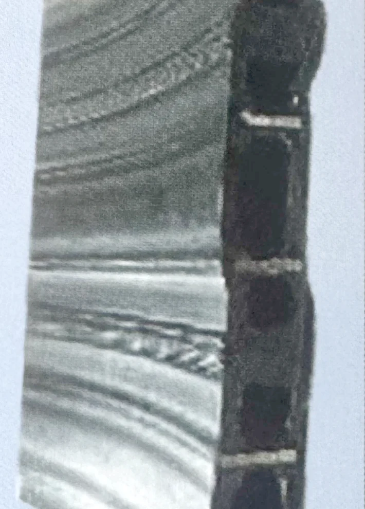
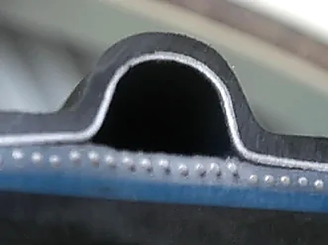
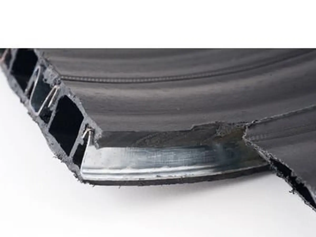
A reinforced polyethylene profile is spiral wound and thermally bonded into a structured wall. Each material layer has a specific engineering job.
Creates the sealed flow surface and separates the conveyed medium from the reinforcement.
Provides the principal structural contribution within the hollow profile.
Completes the composite wall and protects the reinforced structure.
04 / From feature to project value
Published dimensions extend to DN5000, with project-specific capability up to 6 m.
Published tableWall construction and stiffness can be reviewed against the installed ground and loading conditions.
Structure + design basisThe polyethylene flow passage supports drainage environments subject to compatibility review.
Material declarationCoordinated section length can reduce the number of field interfaces requiring control.
Route layoutSocket, sealing, heat-shrink, fusion and electrofusion options support project-specific connection planning.
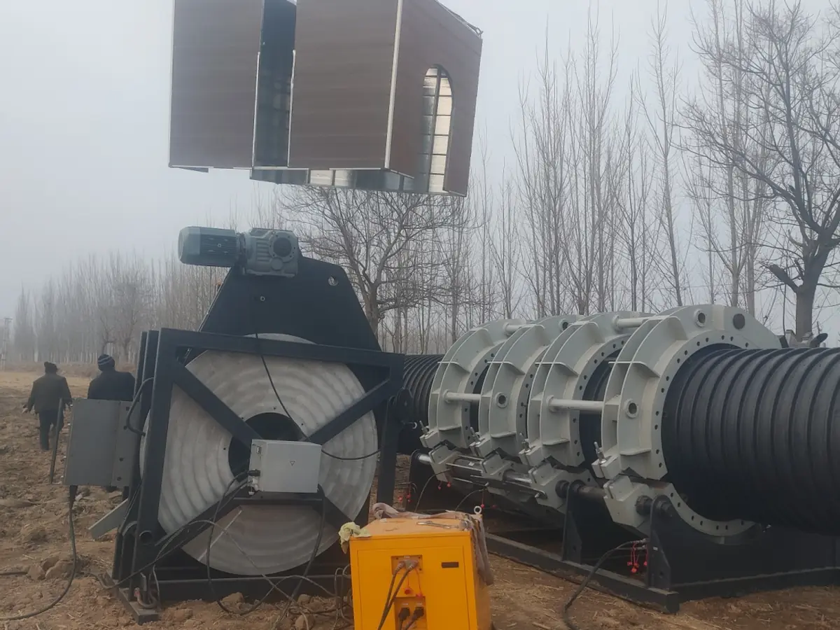
Joint procedureFor projects above 3 m, factory delivery can be compared with on-site manufacturing feasibility.
Logistics study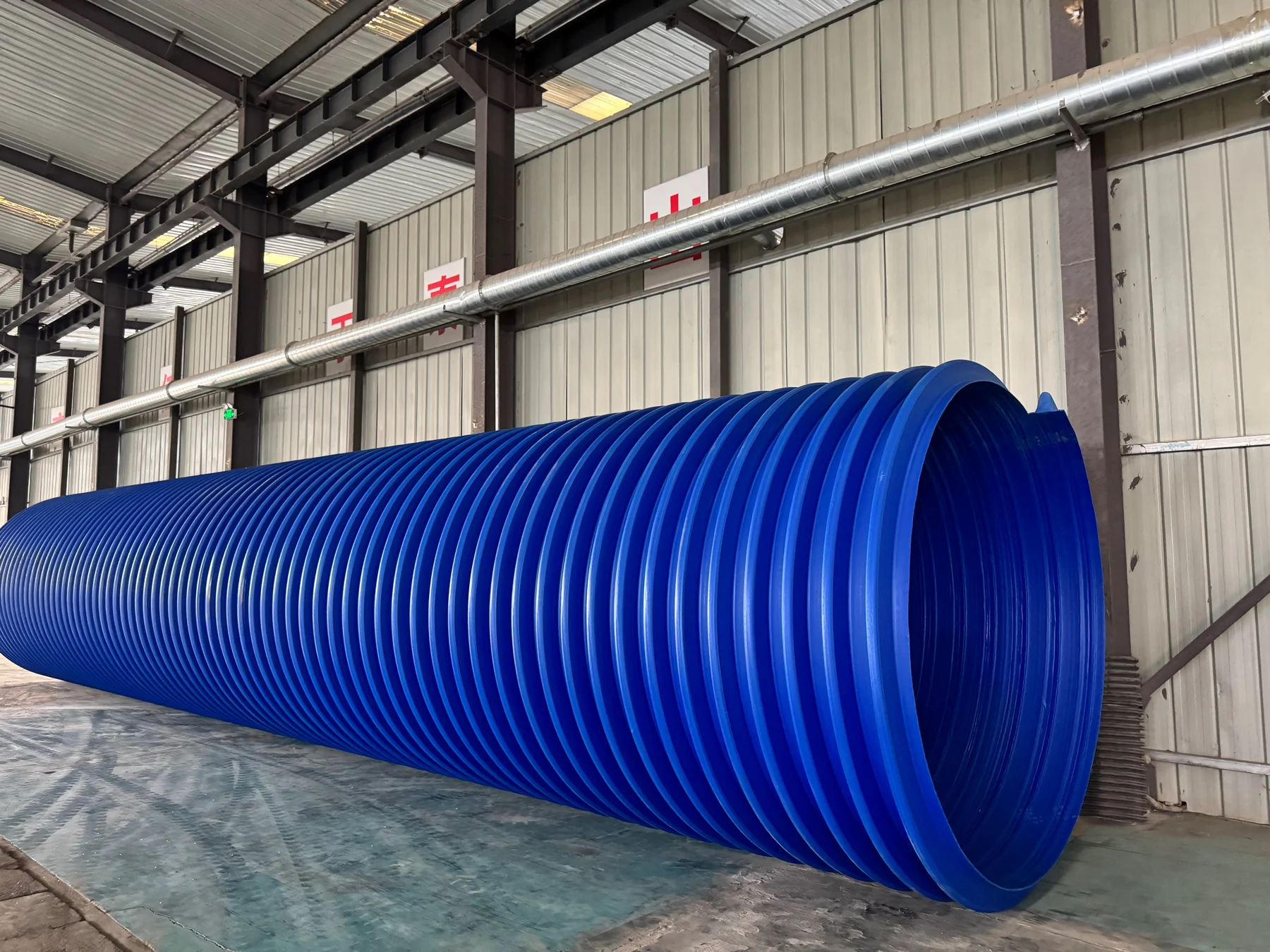
Published dimensional data reaches DN5000. Manufacturing capability can extend to project-specific structured-wall systems up to 6 m after technical review.
05 / Application fit
Application names are the first filter. Flow, burial, loading, ground and jointing complete the decision.
06 / Oversized logistics
For pipe projects above 3 m, compare conventional factory delivery with moving production equipment closer to the project.
Select the conditions that describe your project.
Technical specification table
The technical table lists nominal diameter, minimum average inside diameter and minimum inner-layer wall thickness from DN160 to DN5000. Manufacturing capability extends to project-specific pipe systems up to 6 m.
| Nominal diameter dn (mm) | Minimum average inside diameter dim,min (mm) | Minimum inner-layer wall thickness (mm) |
|---|---|---|
| 160 | 155 | 1.3 |
| 200 | 195 | 1.5 |
| 250 | 245 | 1.8 |
| 300 | 294 | 2.0 |
| 400 | 392 | 2.5 |
| 450 | 441 | 2.8 |
| 500 | 490 | 3.0 |
| 600 | 588 | 3.5 |
| 700 | 673 | 4.0 |
| 800 | 785 | 4.5 |
| 900 | 885 | 5.0 |
| 1000 | 985 | 5.0 |
| 1100 | 1085 | 5.0 |
| 1200 | 1185 | 5.0 |
| 1300 | 1285 | 5.0 |
| 1400 | 1385 | 5.0 |
| 1500 | 1485 | 5.0 |
| 1600 | 1585 | 5.5 |
| 1700 | 1685 | 5.5 |
| 1800 | 1785 | 6.0 |
| 1900 | 1885 | 6.0 |
| 2000 | 1985 | 6.0 |
| 2100 | 2085 | 6.0 |
| 2200 | 2185 | 7.0 |
| 2300 | 2285 | 8.0 |
| 2400 | 2385 | 9.0 |
| 2500 | 2485 | 10.0 |
| 2600 | 2585 | 10.0 |
| 2700 | 2685 | 10.0 |
| 2800 | 2785 | 10.0 |
| 2900 | 2885 | 10.0 |
| 3000 | 2985 | 10.0 |
| 3100 | 3085 | 10.0 |
| 3200 | 3185 | 10.0 |
| 3300 | 3285 | 10.0 |
| 3400 | 3385 | 10.0 |
| 3500 | 3485 | 10.0 |
| 3600 | 3585 | 11.0 |
| 4000 | 3985 | 12.0 |
| 4500 | 4485 | 13.0 |
| 5000 | 4985 | 14.0 |
DN means nominal size; confirm whether the specified series is based on inside diameter (DN/ID) or outside diameter (DN/OD). Do not treat DN as a measured diameter. SN indicates nominal ring stiffness, normally expressed in kN/m²; confirm the test method and required class. PE means polyethylene; HDPE means high-density polyethylene. PE80 and PE100 are material strength classifications, not pressure ratings.
Use the table for preliminary selection. Confirm final dimensions, pipe construction, pressure rating or ring stiffness and compatible joints against the project requirements. Pressure-test results for one specimen do not establish the rating of every diameter or configuration.
08 / Connection & installation
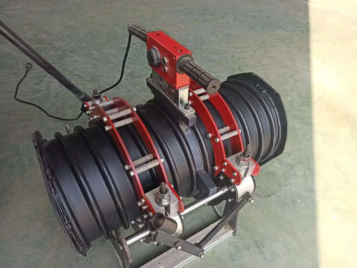
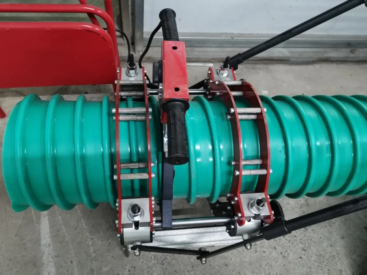
The method must match the composite structure, diameter, duty, working space, equipment and approved procedure.
09 / Evidence chain
15-second proof
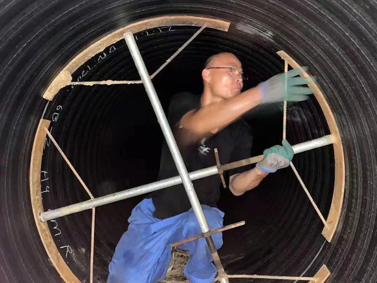
Structured-wall pipe under an excavator — external-loading duty recorded on site.
Cutaway, profile and material-role documentation.
Winding line, dimensional checks and order traceability.
Approved method, qualified people and inspection steps.
Project-specific handling, installation and acceptance evidence.
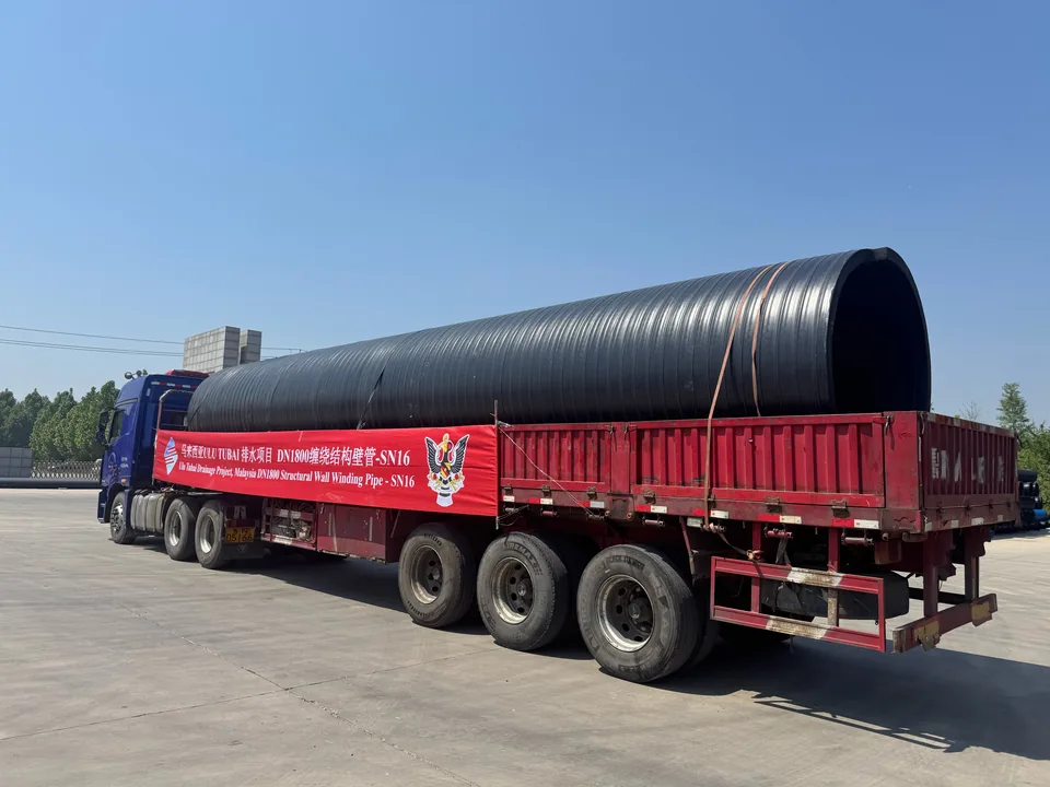
DN1800 spiral-wound structural-wall pipe, SN16, supplied for the Ulu Tubai drainage project in Malaysia for highway construction. Factory dispatch, container-port loading and SIRIM-certified pipes at the Malaysia site are recorded in project photos.
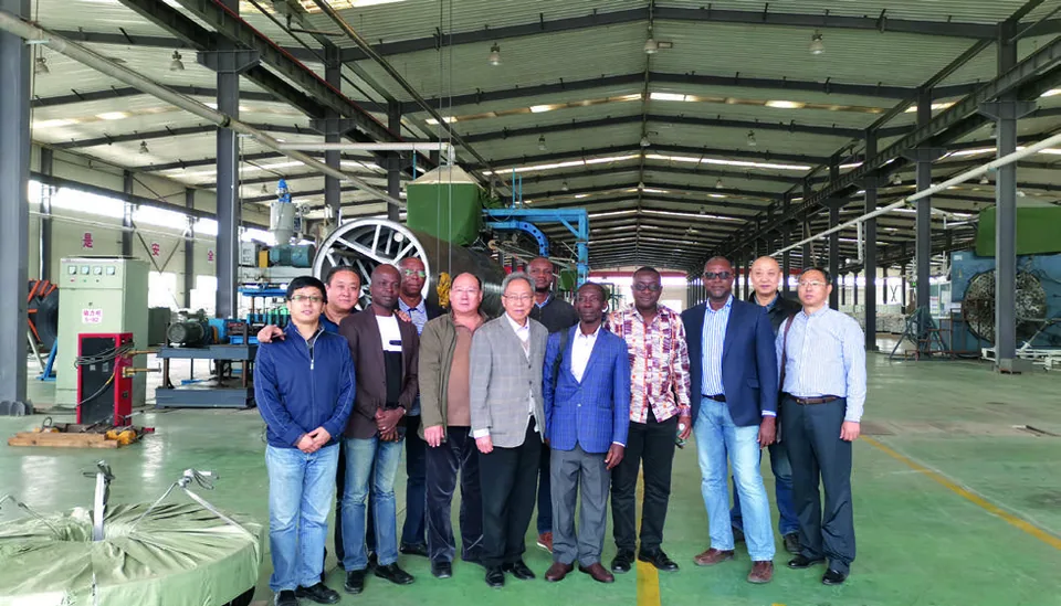
An African customer delegation visiting the Shunfang factory to review large-diameter pipe production for water and drainage project cooperation, under international market development.
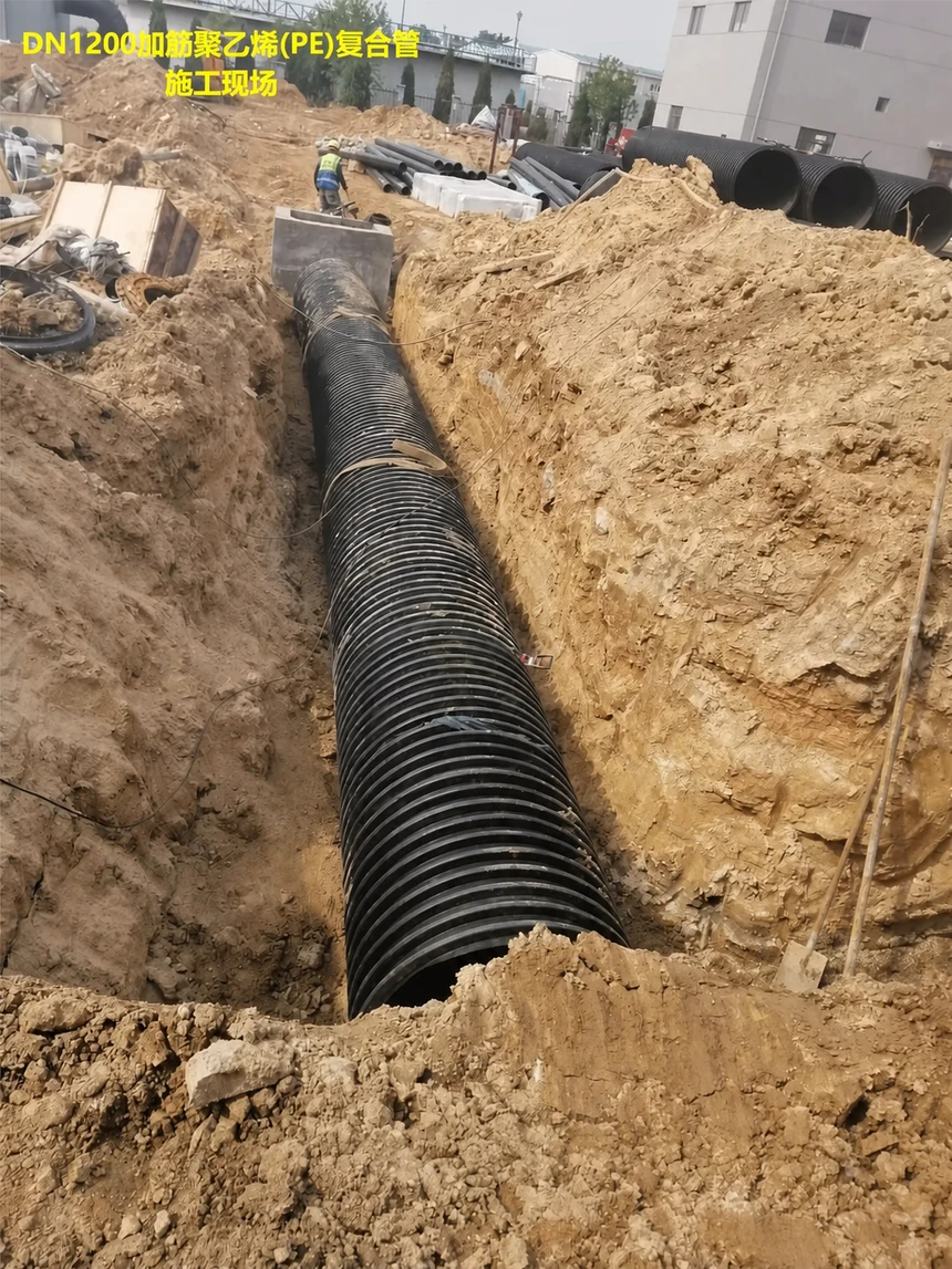
A documented DN1200 reinforced PE composite pipe installation in an excavated trench.
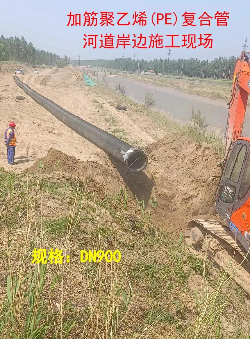
A published DN900 site reference for Shunfang reinforced PE composite pipe.
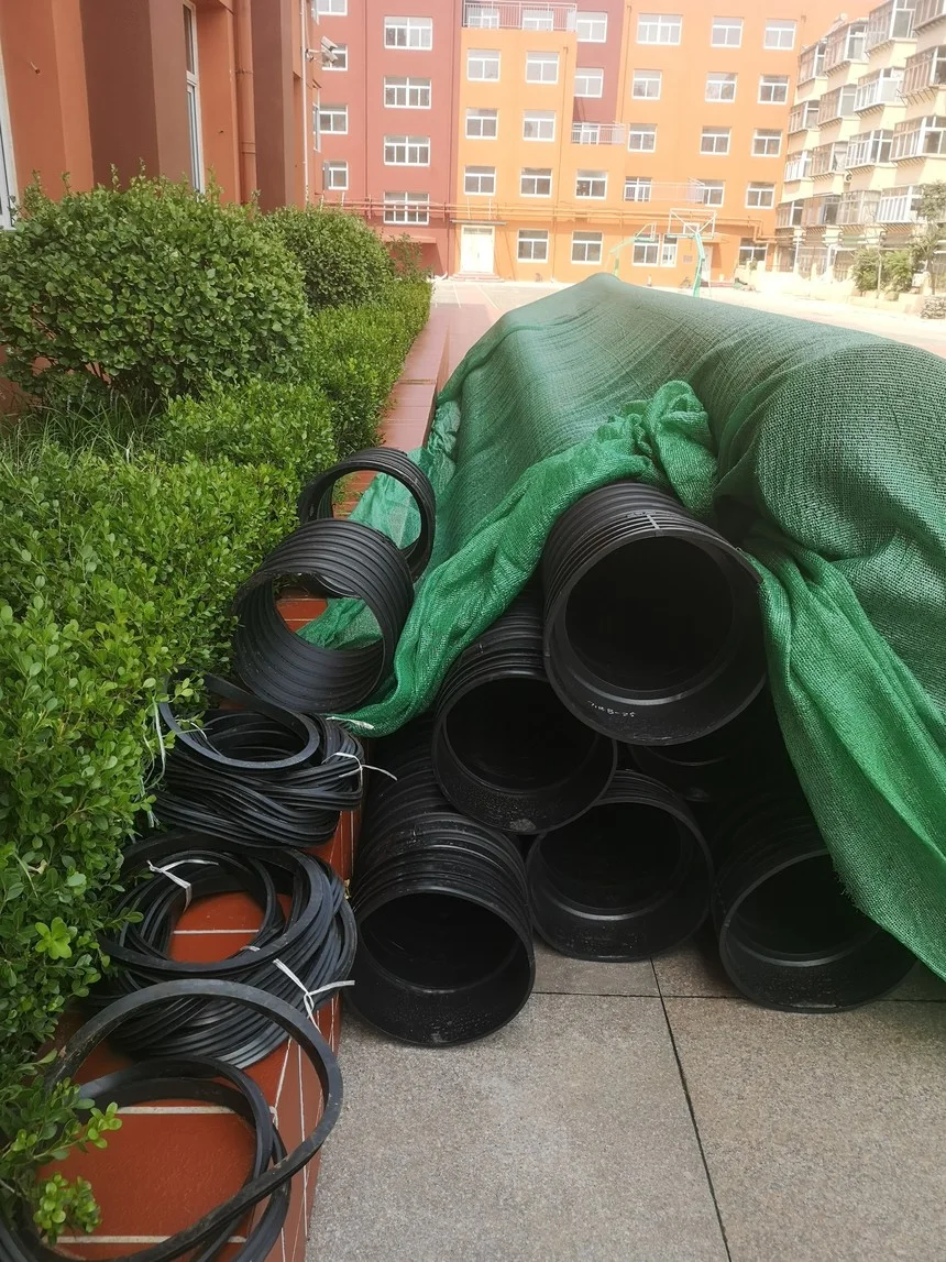
A municipal sewer and stormwater separation reference in Jinan included in the official project archive.
Supply capability
Dedicated reinforced PE composite-pipe (RPEP) lines cover DN110 to DN800. Each line holds its own die, mandrel and cooling-jacket sets, so diameter changes do not stop the full production schedule. Larger diameters follow project-specific wound routes — confirm the route for the specified diameter.
Complete RPEP line · 6 sets of dies, mandrels and cooling jackets · DN110, 125, 160, 200, 225, 250
Standby line · 3 spare sets of dies and mandrels · DN250, 280, 315, 355, 400, 450
Complete RPEP line · 6 sets of dies, mandrels and cooling jackets · DN400, 450, 500
Complete RPEP line · 5 sets of dies, mandrels and cooling jackets · DN400, 450, 500, 560, 600, 630
Complete RPEP line · 5 sets of dies, mandrels and cooling jackets · DN500, 560, 630, 710, 800
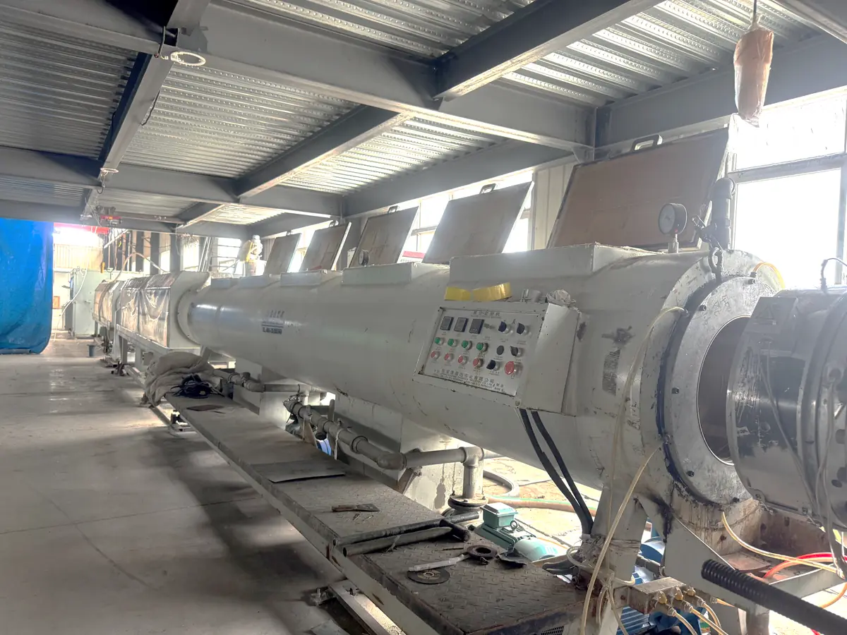
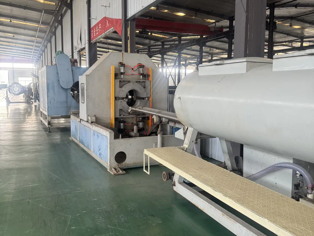
Large-diameter RPEP equipment on the factory floor, backed by incoming inspection records for every production batch.
10 / Digital-to-field workflow
Application, flow, diameter basis, stiffness, quantity, location, schedule and drawings.
Separate gravity requirements from pressure duty and identify missing design information.
Review wall structure, connection, production route, fittings and inspection basis.
Assess factory delivery, oversized handling and on-site production feasibility when relevant.
Agree manufacturing, dimensional checks, traceability and documentation requirements.
Coordinate delivery, jointing procedure and installation guidance within the agreed scope.
11 / Project questions
It is reviewed for gravity-flow sewer, stormwater, drainage, flood-control, casing and marine-outfall duties where flow capacity and buried structural performance both matter.
It supports project-specific systems. Final configuration is developed around flow, diameter basis, wall structure, stiffness, burial, connection and logistics.
Flow, diameter, ring stiffness, burial depth, soil, groundwater, traffic loading, connection and installation quality must be considered together.
No. The approved method depends on pipe structure, diameter, access, power, sealing duty and project procedure.
Drainage PE composite pipe
Drainage reinforced PE composite pipe uses spiral-wound strips with steel-wire-reinforced hollow ribs. Flow, ring stiffness, ground conditions and jointing guide product selection.
Download the English brochure (PDF) ↓ · Download centre →
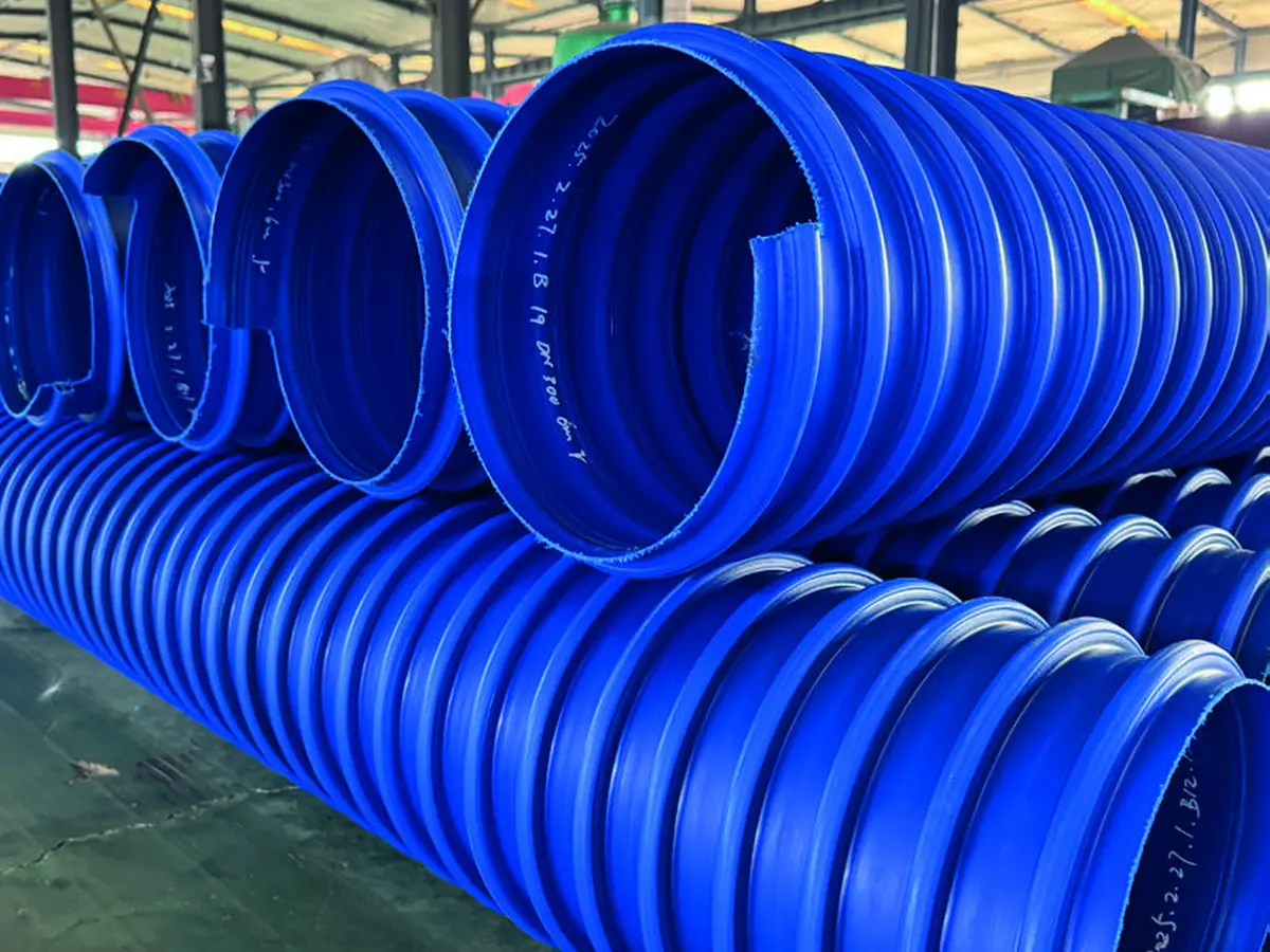
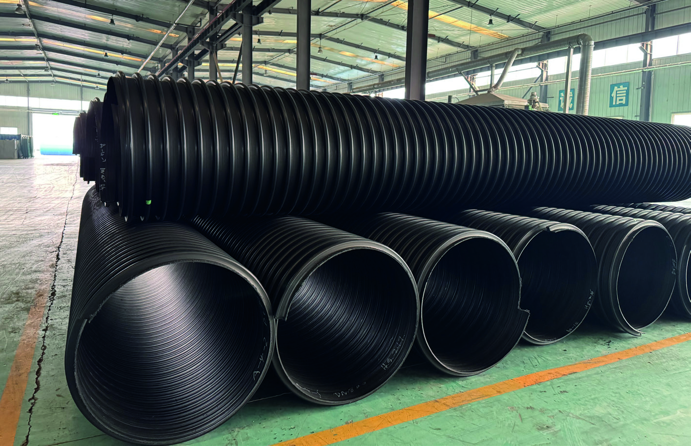
The hollow-rib strip contains steel-wire reinforcement. Spiral winding, bonding and an outer PE protective layer form the drainage wall. The published dimensional table covers DN160–DN5000.
01 · Overview & structure
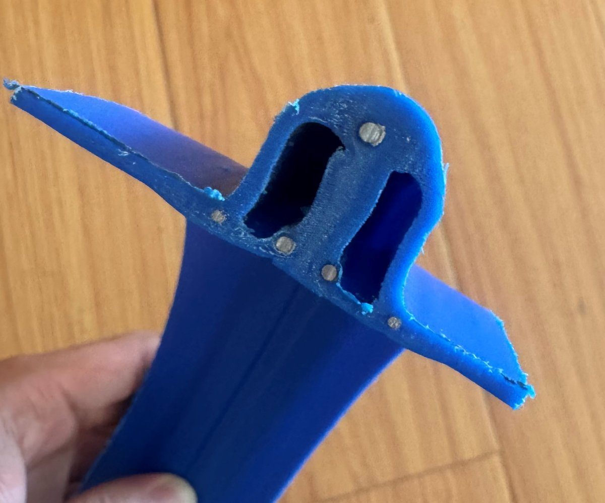
Drainage reinforced PE composite pipe is wound from hollow-rib steel-wire-reinforced strips for diameters above 5 m; the layered rib-wire structure reaches the specified ring stiffness, produced entirely from virgin material.
A screw extruder forms double-chamber ribbed strips, which are spiral-wound and hot-bonded before outer wire and PE protection layers are added.
Hollow rib cavities save weight; the metal dots in section are the longitudinal wires, fully encased in PE with no exposure.
Spiral-wound blue ribbed pipe body; the external ribs are the source of ring stiffness.
02 / Product characteristics
 01
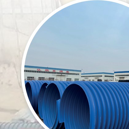
Virgin PE100/PE80 high-molecular-weight polyethylene gives flexibility, corrosion and fatigue resistance and smooth walls. Light yet strong; no recycled material.
 02
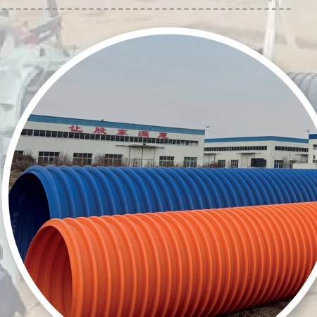
Spiral-wound steel-wire-reinforced strips set the diameter by the steel core mould, enabling large-diameter production.
 03
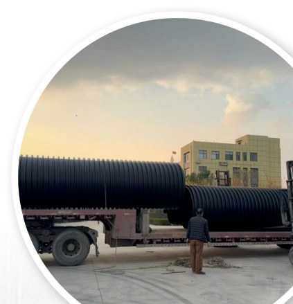
Adjacent strips are hot-bonded with dedicated adhesive and pressed into one integrated wall.
 04
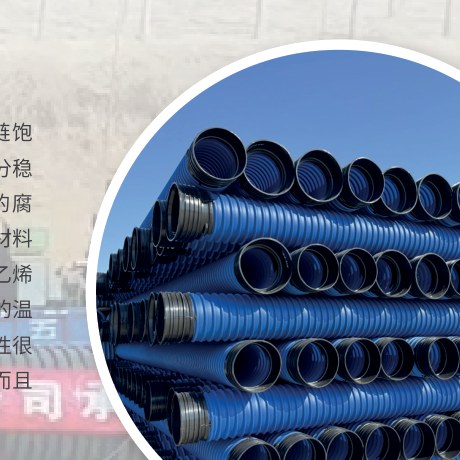
Carbon spring-steel wire exceeds 1800 MPa tensile strength — about 4.5 times ordinary steel (approx. 400 MPa) — giving strong bending resistance, high ring stiffness and elastic recovery after loading.
 05
Saturated long-chain PE structure with fully encased wire resists acids, alkalis, salts and solvents; 40-year buried service life stated.
03 / Drainage-pipe jointing
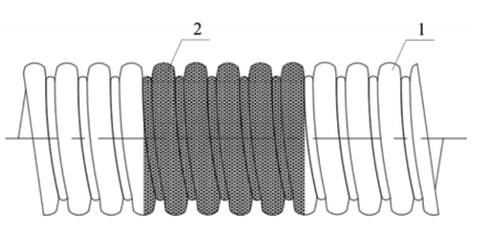
A sized heat-shrink sleeve lined with hot-melt adhesive is heated with an LPG flame to shrink and bond over both pipe ends. Callouts: 1 pipe; 2 heat-shrink sleeve.
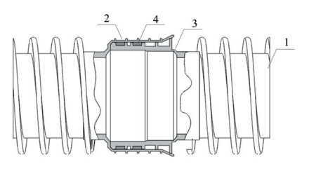
One spigot end with sealing rings enters the socket end and is pushed home with joining equipment. Callouts: 1 pipe; 2 socket; 3 spigot; 4 sealing ring.
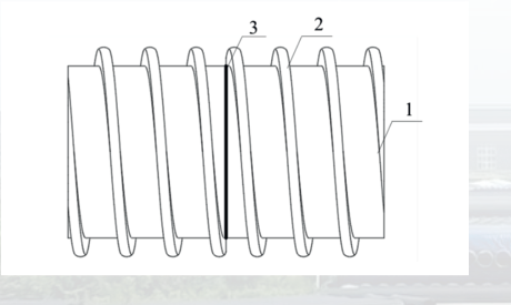
Cleaned and squared ends are welded with dedicated butt-fusion equipment for a reliable watertight joint. Callouts: 1 pipe; 2 reinforcing rib; 3 butt weld.
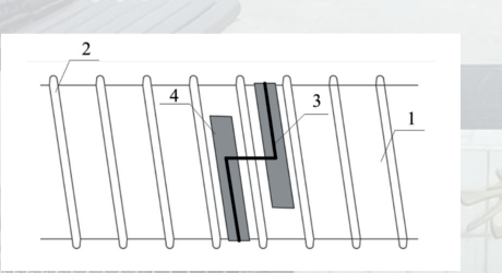
The electrofusion band runs at least 1.2 turns along the rib groove with internal support and external clamps; longitudinal seams are finished by extrusion welding. Callouts: 1 pipe; 2 rib; 3 joint; 4 band.
04 / Physical performance
| No. | Item | Unit | Requirement |
|---|---|---|---|
| 1# | Appearance | / | Smooth, uniform appearance |
| 2# | Tensile strength | MPa | ≥20 |
| 3# | Elongation at break | % | ≥200 |
| 4# | Flexural modulus | MPa | ≥1500 |
| 5# | Ring stiffness | kN/m² | ≥12.5 (SN12.5) |
| 6# | Ring stiffness | kN/m² | ≥16 (SN16) |
| 7# | Impact resistance | % | ≤10 |
| 8# | Creep ratio | % | ≤3 |
| 9# | Ring flexibility | / | No reverse bending or cracking; tearing under 75 mm |
| 10# | Oven test | / | No bubbles, delamination or cracking |
| 11# | Oxidation induction time (OIT) | Min | ≥30 |
| 12# | Longitudinal reversion | / | ≤3%, no delamination or cracking |
05 / Applications
Standards
Product standard for reinforced PE composite pipe.
Buried PE structured-wall piping systems, Part 2: spiral-wound structured-wall pipe.
06 / Projects
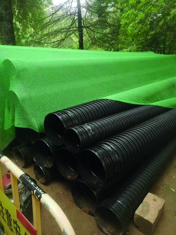
2022 project · DN300–DN600 · SN12.5 · 30 km of pipeline.
DN1600 large-diameter drainage installation.
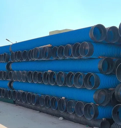
DN2600 extra-large drainage pipeline.
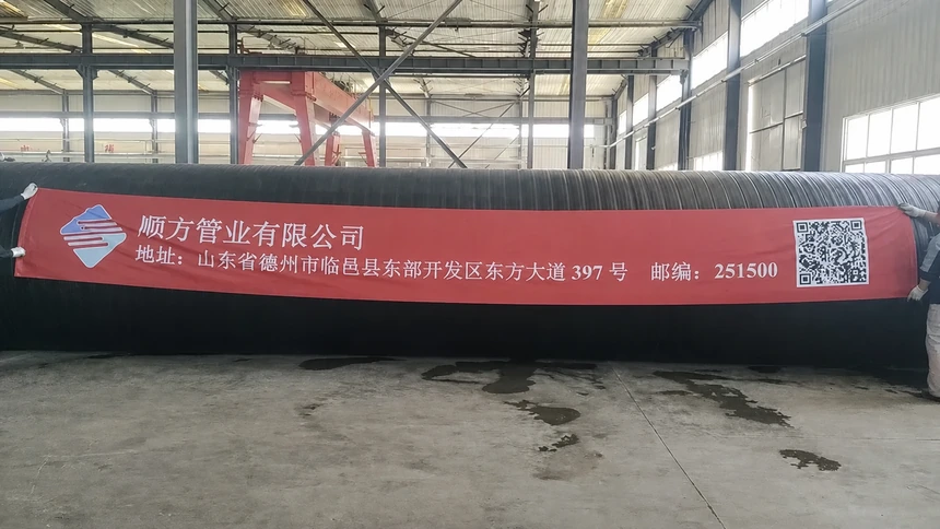
DN1800 spiral-wound structured-wall pipes exported to Malaysia.
12 / Your project basis
We will review product fit, missing design inputs and the practical manufacturing and delivery route. Website information is not treated as final project design.
PROJECT ENQUIRY
Application · medium · diameter · pressure or ring stiffness · quantity · destination