Is the line internally pressurized?
Water transmission, regional transfer and project-specific industrial water duty enter this system route.
 largeHDPEpipe.com
Start a project ↗
Pressurized flow · Core system 02
A steel-wire-reinforced PE composite pressure system for water transmission and demanding pressurized duties—selected around medium, diameter, pressure, jointing and installation.
01 / Project fit check
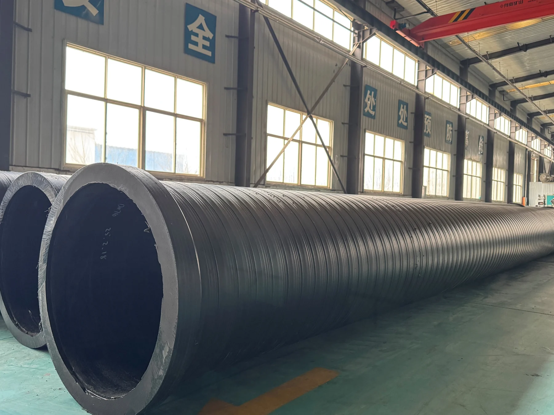
Water-supply reinforced PE composite pipe serves water transmission and other pressurized duties. Polyethylene forms the flow passage and protective layers, while steel wire reinforces the pipe wall.
Water transmission, regional transfer and project-specific industrial water duty enter this system route.
Medium, operating pressure, design pressure, surge, temperature and design life form the technical basis.
Diameter, composite structure, site equipment and the governing standard determine the approved jointing path.
02 / The cost of assumption
One test result proves one configuration—not an entire catalogue.
Operating, design, test and surge pressure are different engineering inputs.
Not every published diameter is offered at every listed pressure class.
This system must not be specified as ordinary solid-wall PE pipe.
Pipe, fittings, transitions and joints share pressure-boundary responsibility.
03 / What it is
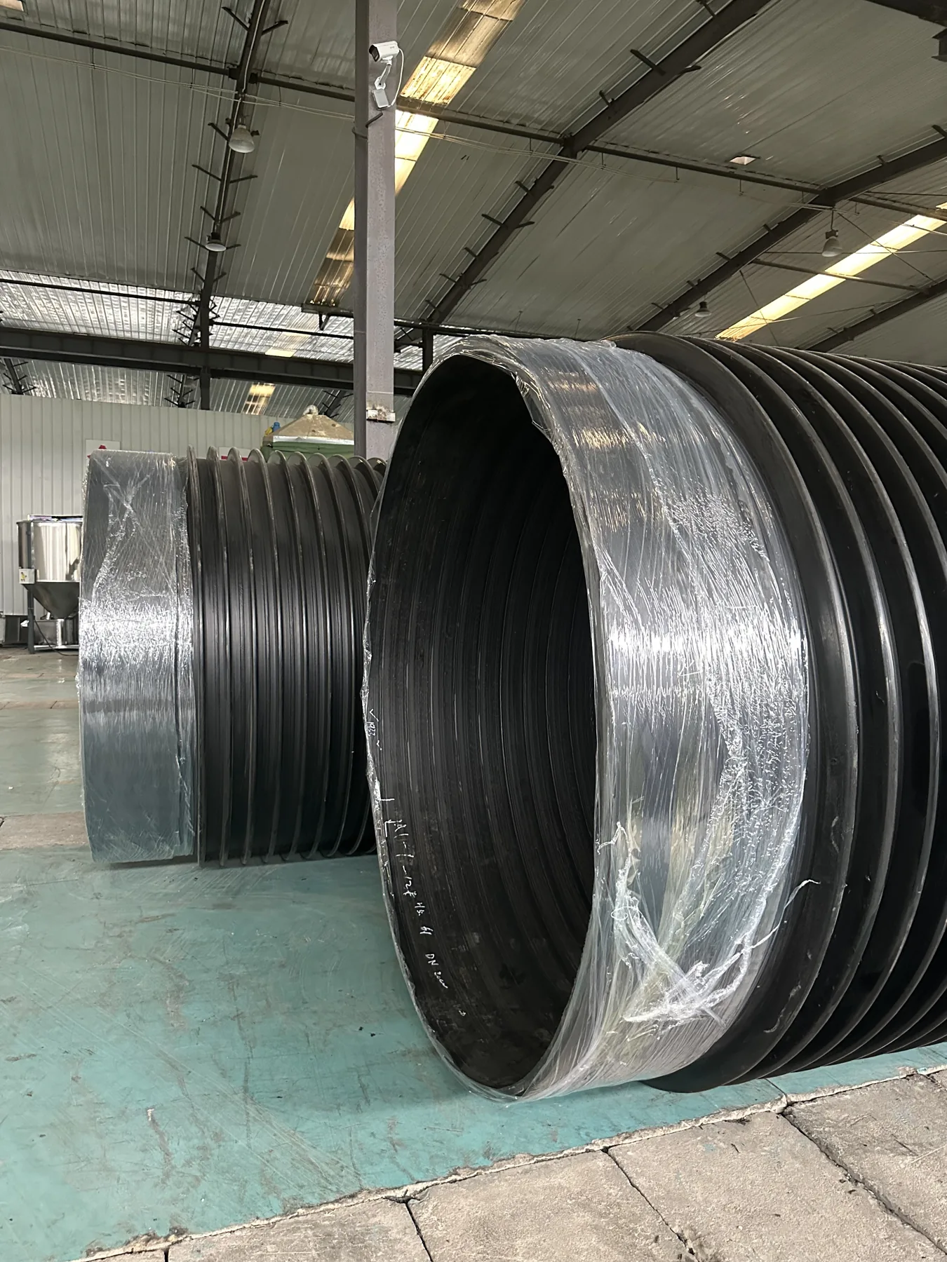
Polyethylene provides the sealed, corrosion-resistant medium path and protective system. Steel-wire reinforcement provides the principal strengthening function.
Creates the fluid-contact surface and corrosion-resistant bore.
Changes how the product carries structural demand compared with ordinary solid-wall HDPE.
Bonding and protective polyethylene complete the integrated wall and fitting interface.
04 / From feature to project value
Provides a distinct structural route where an ordinary solid-wall comparison is incomplete.
Cutaway + structureSelect the matching pressure class and wall thickness for each diameter.
Dimensional tableAvailable class and wall combinations can be checked instead of relying on a blanket rating.
Combination matrixThe polyethylene flow passage supports water and project-reviewed industrial duties.
Material declarationButt fusion, electrofusion and sleeve options support planning around diameter and site conditions.
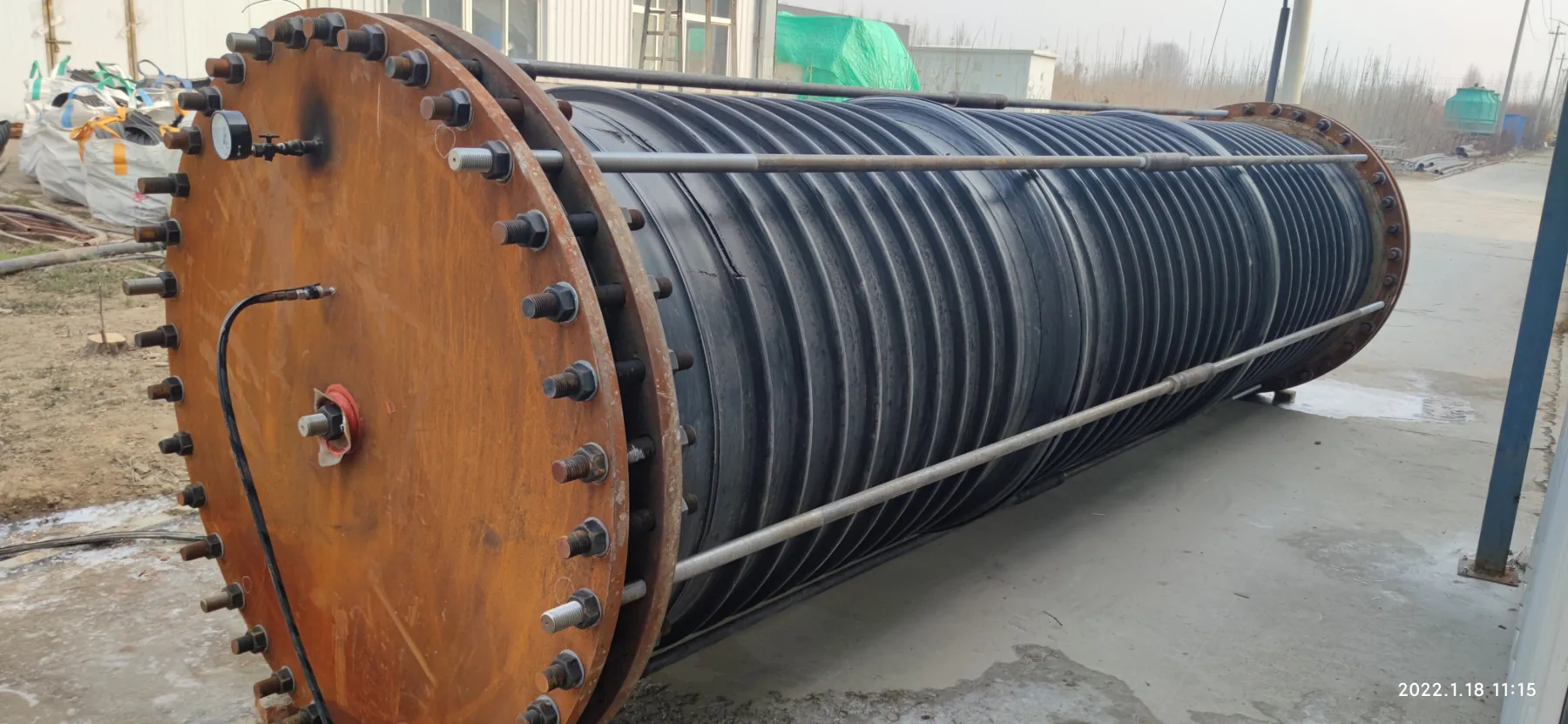
Joint procedureThe DN560 record creates a specific discussion point instead of an unqualified high-pressure claim.
Test report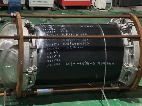
DN560 · 1.6 MPa design pressure · 2.4 MPa pressure holding for 118 hours · 3.4 MPa maximum test pressure. This result is not a universal rating for other configurations.
05 / Application fit
The application defines the questions; project conditions determine the final pressure-pipe configuration.
06 / Pressure-basis review
Select the information already available. The result shows whether the enquiry is ready for a focused technical review.
Select the conditions that describe your project.
Technical specification table
Scroll the table horizontally to see every pressure class and wall value.
Water-supply reinforced PE composite pipe is available in nominal diameters from DN50 to DN5000. The table provides wall thicknesses for pressure classes from 0.4 to 2.5 MPa (4 to 25 bar); available combinations vary by diameter.
| Selection item | Range | Application note |
|---|---|---|
| Nominal diameter | DN50–DN5000 | Select the matching pipe and joint configuration |
| Pressure classes shown | 0.4–2.5 MPa | Available wall values vary by diameter |
| Nominal diameter dn (mm) | Minimum average inside diameter dim,min (mm) | Pressure (MPa) / nominal wall thickness en (mm) | ||||||
|---|---|---|---|---|---|---|---|---|
| 0.4 4.0 bar | 0.6 6.0 bar | 0.8 8.0 bar | 1.0 10.0 bar | 1.6 16.0 bar | 2.0 20.0 bar | 2.5 25.0 bar | ||
| 50 | 45 | - | - | - | 2.1 | 2.5 | 2.8 | 3.2 |
| 63 | 58 | - | - | 2.2 | 2.4 | 2.7 | 3.0 | 3.4 |
| 75 | 69 | - | 2.5 | 2.6 | 2.7 | 3.0 | 3.2 | 3.6 |
| 90 | 83 | - | 3.0 | 3.0 | 3.1 | 3.4 | 3.6 | 3.9 |
| 110 | 102 | - | 3.6 | 3.6 | 3.7 | 4.0 | 4.2 | 4.4 |
| 125 | 116 | - | 4.0 | 4.0 | 4.1 | 4.4 | 4.6 | 4.8 |
| 160 | 150 | - | 4.8 | 4.5 | 4.9 | 5.4 | 5.6 | 5.8 |
| 200 | 176 | - | 4.0 | 4.8 | 5.0 | 5.5 | 6.0 | 6.5 |
| 225 | 198 | - | 4.0 | 5.0 | 5.5 | 6.0 | 6.5 | 7.0 |
| 250 | 220 | 4.0 | 5.0 | 5.5 | 6.0 | 6.5 | 7.0 | 8.0 |
| 280 | 247 | 5.0 | 5.5 | 6.0 | 6.5 | 7.0 | 8.0 | 9.0 |
| 315 | 278 | 5.5 | 6.0 | 6.5 | 7.0 | 8.0 | 9.0 | 10.0 |
| 350 | 308 | 6.0 | 7.0 | 8.0 | 9.0 | 10.0 | 11.0 | 12.0 |
| 400 | 353 | 8.0 | 9.0 | 10.0 | 11.0 | 12.0 | 13.0 | 14.0 |
| 450 | 397 | 9.0 | 10.0 | 11.0 | 12.0 | 13.0 | 14.0 | 15.0 |
| 500 | 441 | 10.0 | 11.0 | 12.0 | 13.0 | 14.0 | 15.0 | 16.0 |
| 560 | 494 | 11.0 | 12.0 | 13.0 | 14.0 | 15.5 | 17.0 | 18.5 |
| 630 | 556 | 12.0 | 13.0 | 14.0 | 15.0 | 17.0 | 19.0 | 21.0 |
| 710 | 626 | 13.0 | 14.0 | 15.5 | 17.0 | 19.0 | 21.0 | 23.0 |
| 800 | 706 | 14.0 | 15.0 | 17.0 | 19.0 | 21.0 | 23.0 | 25.0 |
| 900 | 794 | 15.0 | 16.0 | 18.0 | 20.0 | 22.0 | 24.0 | 28.0 |
| 1000 | 882 | 16.0 | 17.0 | 19.0 | 21.0 | 23.0 | 25.0 | 30.0 |
| 1200 | 1095 | 18.0 | 19.0 | 21.0 | 23.0 | 25.0 | 27.0 | - |
| 1400 | 1235 | 20.0 | 21.0 | 23.0 | 25.0 | 27.0 | 29.0 | - |
| 1500 | 1324 | 21.0 | 22.0 | 24.0 | 26.0 | 28.0 | 31.0 | - |
| 1600 | 1412 | 22.0 | 23.0 | 25.0 | 27.0 | 29.0 | 33.0 | - |
| 1800 | 1588 | 24.0 | 25.0 | 27.0 | 29.0 | 31.0 | - | - |
| 2000 | 1765 | 26.0 | 27.0 | 29.0 | 31.0 | 33.0 | - | - |
| 2250 | 1986 | 27.0 | 28.0 | 30.0 | 32.0 | 34.5 | - | - |
| 2400 | 2118 | 28.0 | 29.0 | 31.0 | 33.0 | 36.0 | - | - |
| 2800 | 2471 | 30.0 | 32.0 | 34.0 | 36.0 | - | - | - |
| 3200 | 2824 | 32.0 | 34.0 | 36.0 | 40.0 | - | - | - |
| 3600 | 3176 | 34.0 | 36.0 | 40.0 | 43.0 | - | - | - |
| 4000 | 3529 | 38.0 | 42.0 | 46.0 | - | - | - | - |
| 4500 | 3971 | 44.0 | 48.0 | 52.0 | - | - | - | - |
| 5000 | 4412 | 48.0 | 52.0 | 56.0 | - | - | - | - |
A dash means that this diameter and pressure combination has no standard wall value in the table. Contact our technical team for other requirements, including 3.0 MPa.
DN means nominal size; confirm whether the specified series is based on inside diameter (DN/ID) or outside diameter (DN/OD). Do not treat DN as a measured diameter. SN indicates nominal ring stiffness, normally expressed in kN/m²; confirm the test method and required class. PE means polyethylene; HDPE means high-density polyethylene. PE80 and PE100 are material strength classifications, not pressure ratings.
Use the table for preliminary selection. Confirm final dimensions, pipe construction, pressure rating or ring stiffness and compatible joints against the project requirements. Pressure-test results for one specimen do not establish the rating of every diameter or configuration.
08 / Connection & installation
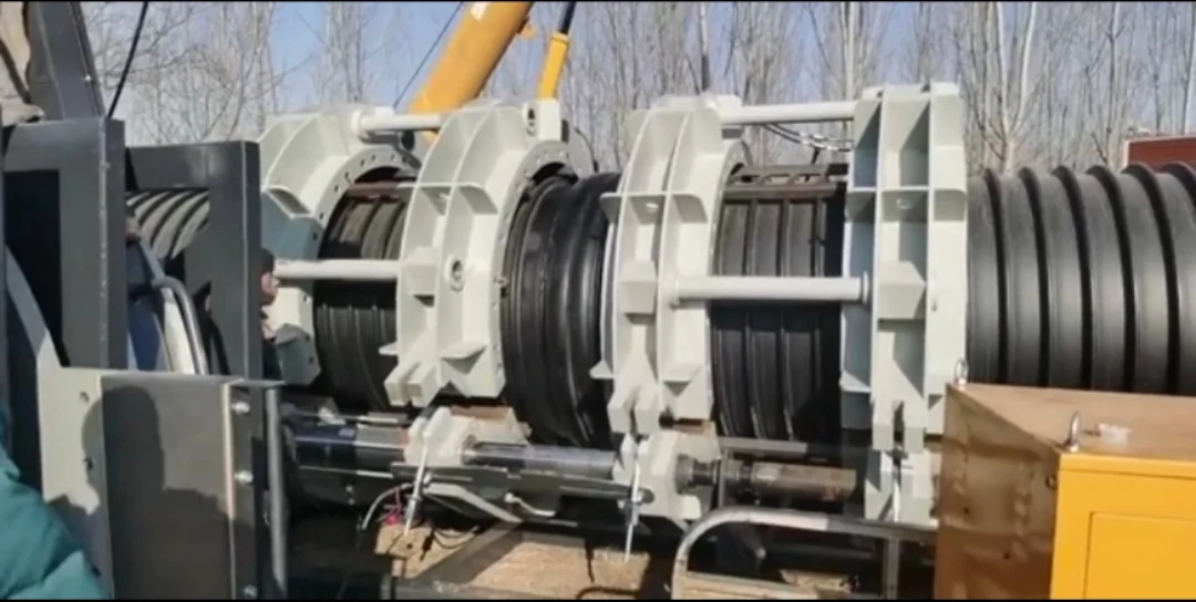
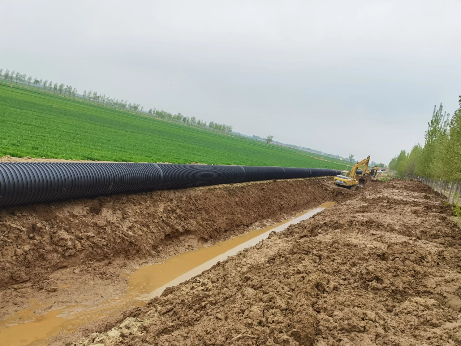
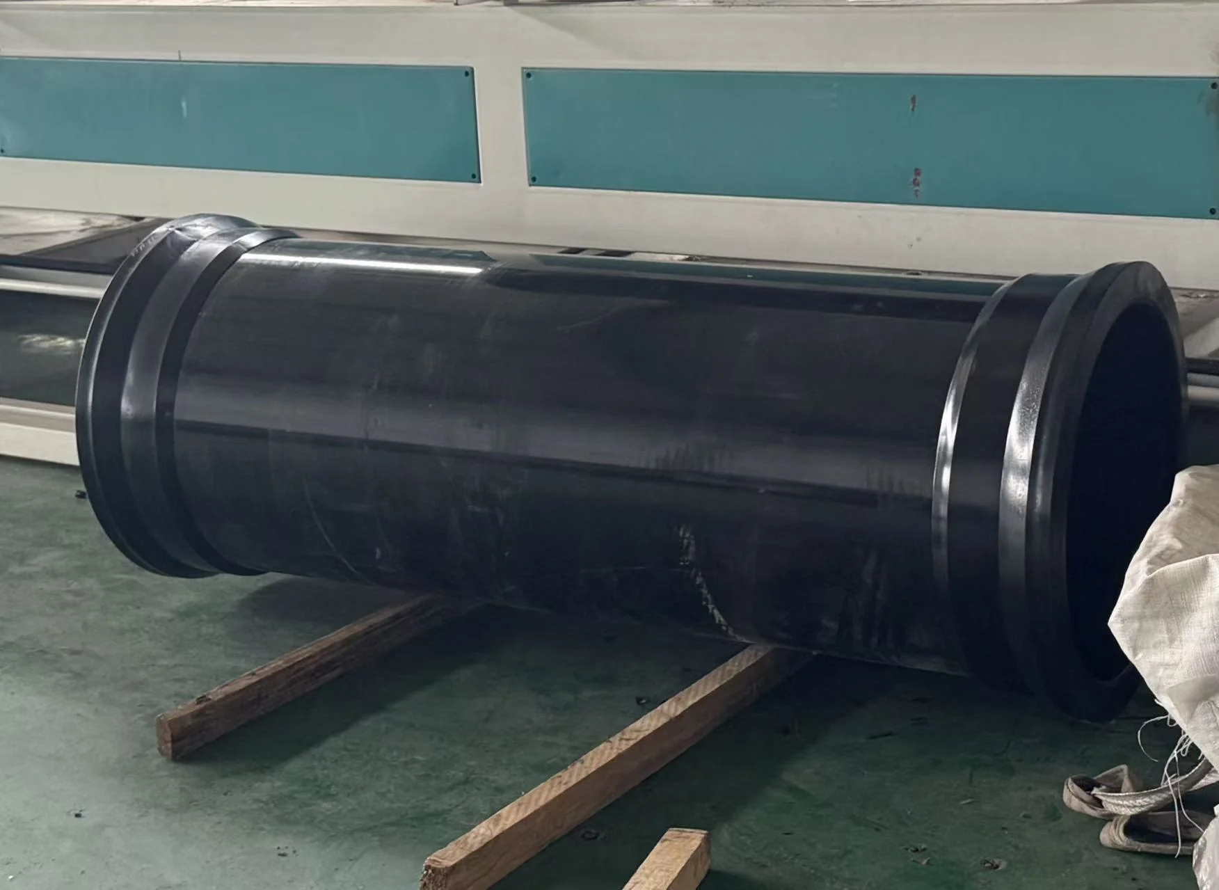
The method must match the composite structure, diameter, duty, working space, equipment and approved procedure.
09 / Evidence chain
Product name, composite structure and material declarations.
Diameter, pressure class and matching wall combination.
Test basis, report, equipment and configuration traceability.
Joint procedure, installation evidence and acceptance scope.
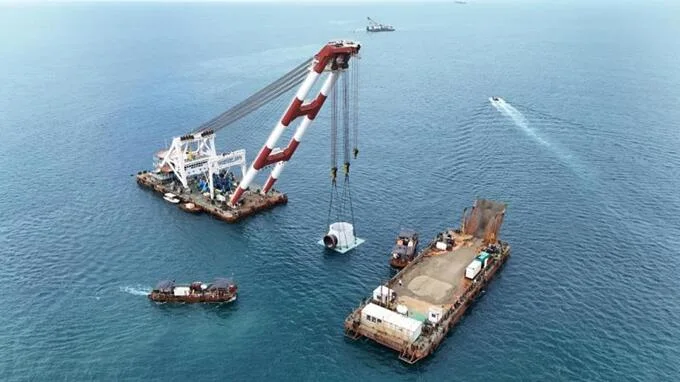
A completed seawater-circulation project with 2 × 600 m runs of DN2400 pipe, rated at 1.0 MPa. Delivery included onshore prefabrication and marine float-out and positioning.
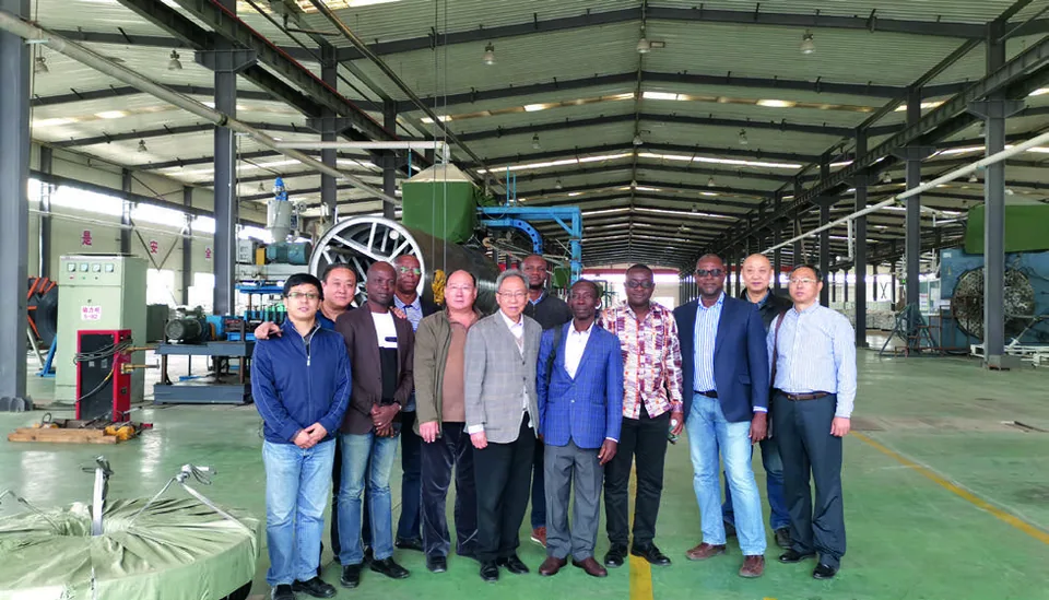
An African customer delegation visiting the Shunfang factory to review large-diameter pipe production for water and drainage project cooperation, under international market development.

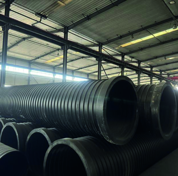
A marine high-pressure water pipeline supplied for an Israel customer, published in the company project presentation under international market references. Photo shows the customer inspecting the large-diameter pipe bore at the factory.
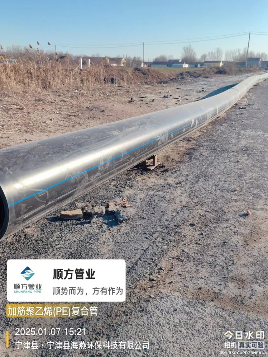
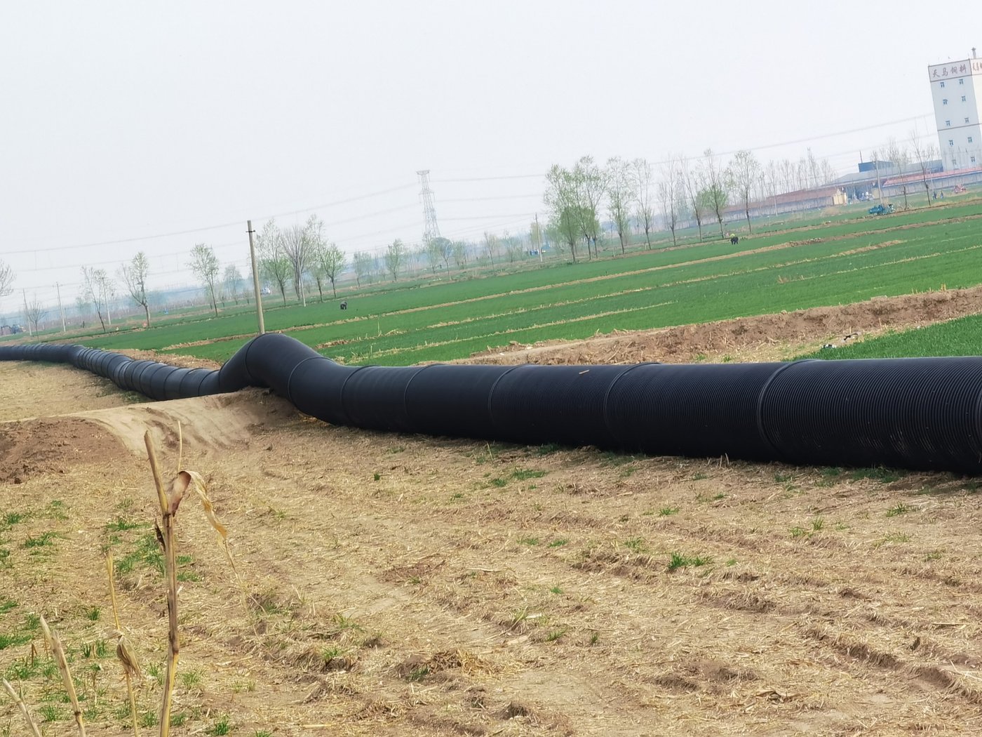
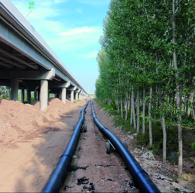
A published DN630 pressure-pipeline site reference showing the long pipe string prepared for pullback installation.
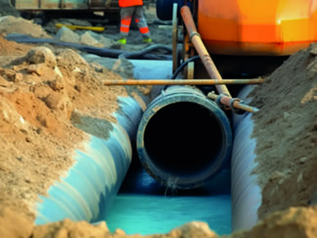
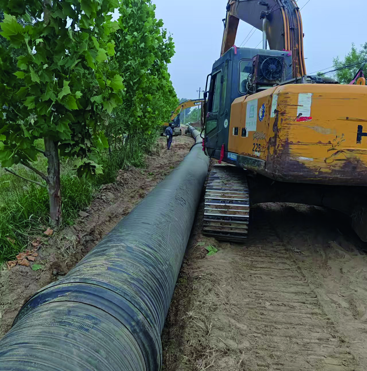
A DN500 water-supply construction reference illustrating on-site pipe handling and alignment.
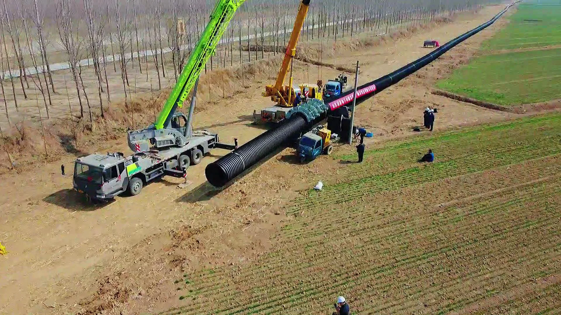
A large-diameter water-transfer project showing lifting, alignment and field assembly of long pipe sections.
Supply capability
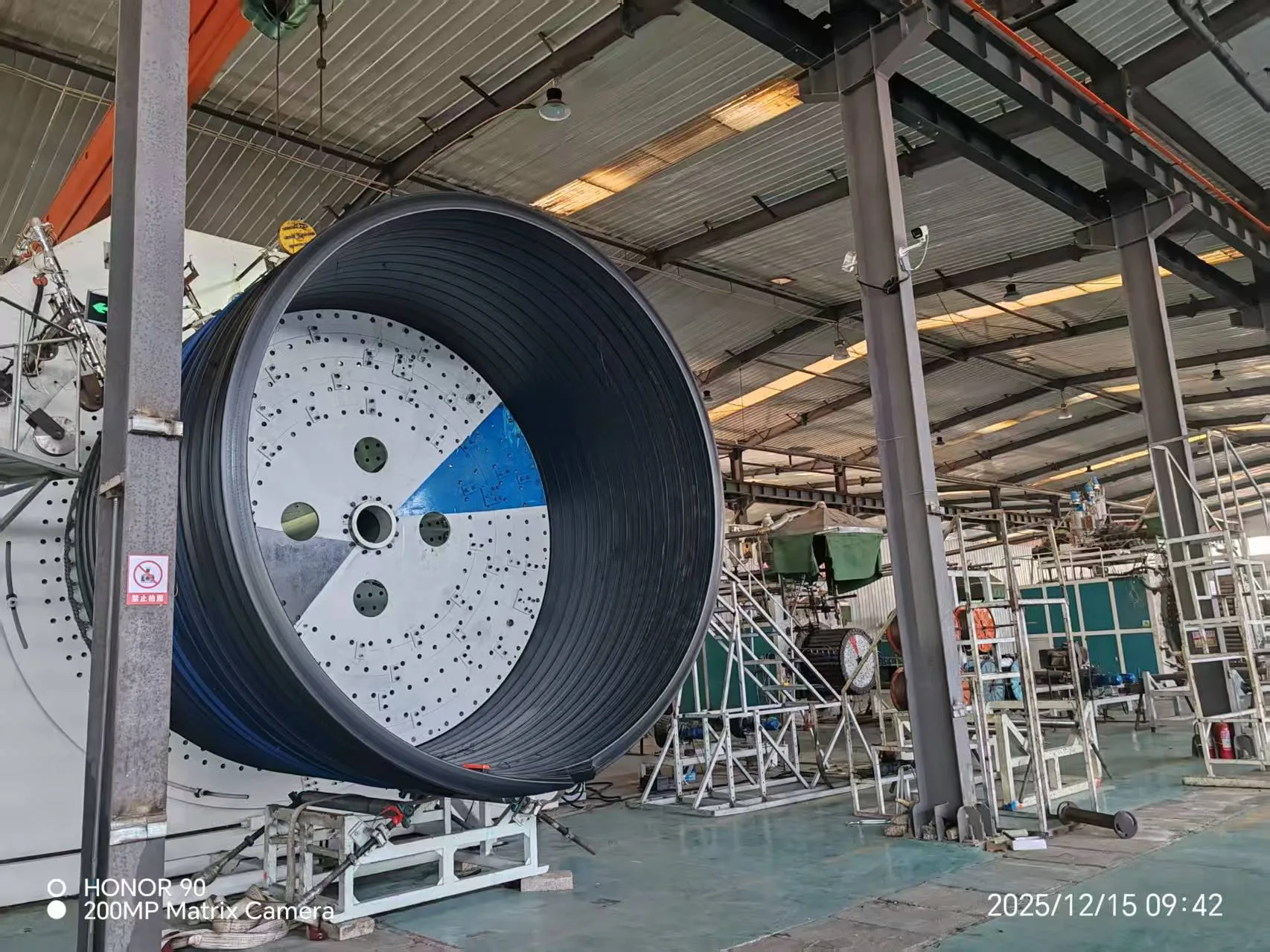
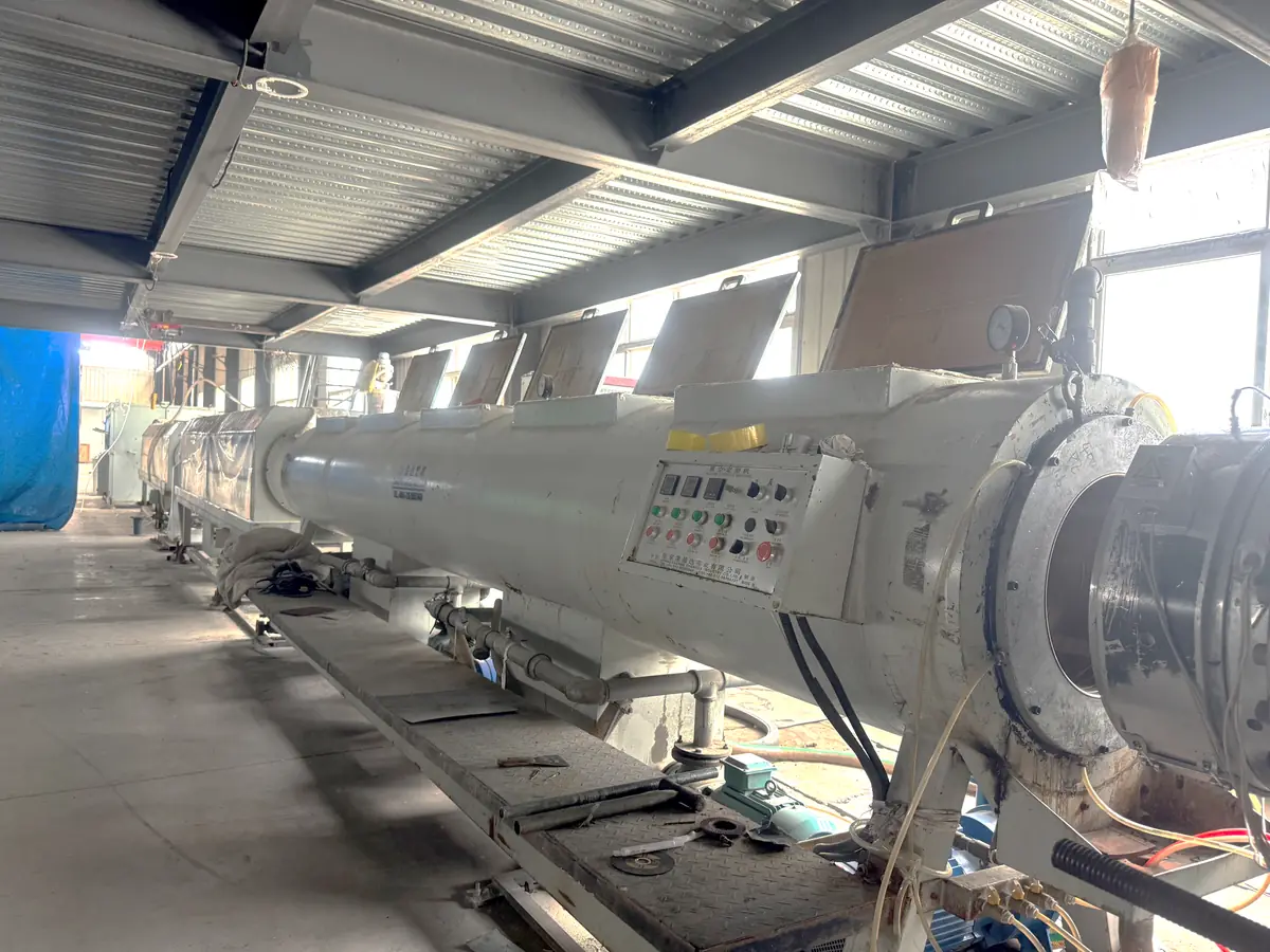
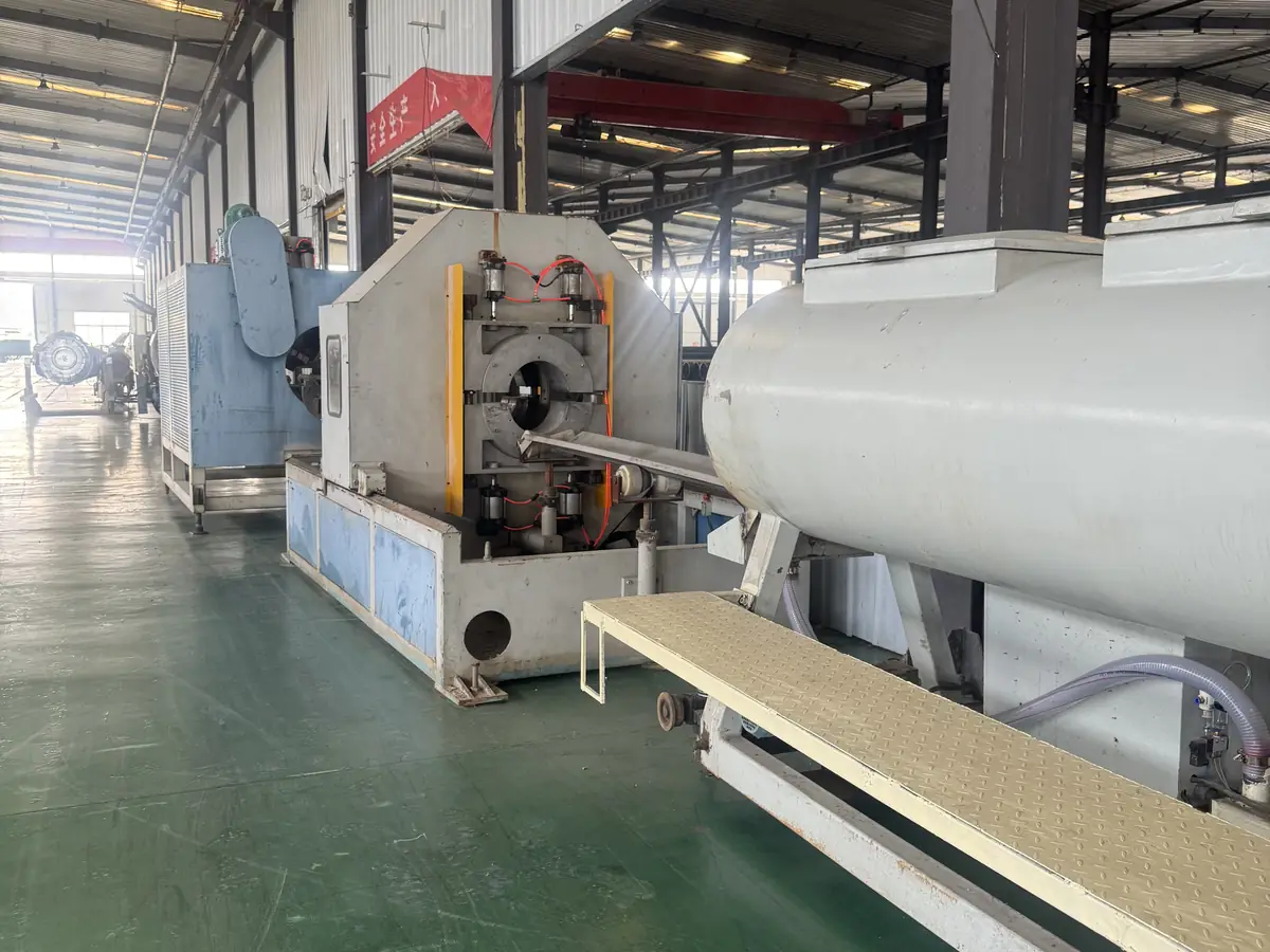
Dedicated reinforced PE composite-pipe (RPEP) lines cover DN110 to DN800. Each line holds its own die, mandrel and cooling-jacket sets, so diameter changes do not stop the full production schedule. Larger diameters follow project-specific wound routes — confirm the route for the specified diameter.
Complete RPEP line · 6 sets of dies, mandrels and cooling jackets · DN110, 125, 160, 200, 225, 250
Standby line · 3 spare sets of dies and mandrels · DN250, 280, 315, 355, 400, 450
Complete RPEP line · 6 sets of dies, mandrels and cooling jackets · DN400, 450, 500
Complete RPEP line · 5 sets of dies, mandrels and cooling jackets · DN400, 450, 500, 560, 600, 630
Complete RPEP line · 5 sets of dies, mandrels and cooling jackets · DN500, 560, 630, 710, 800
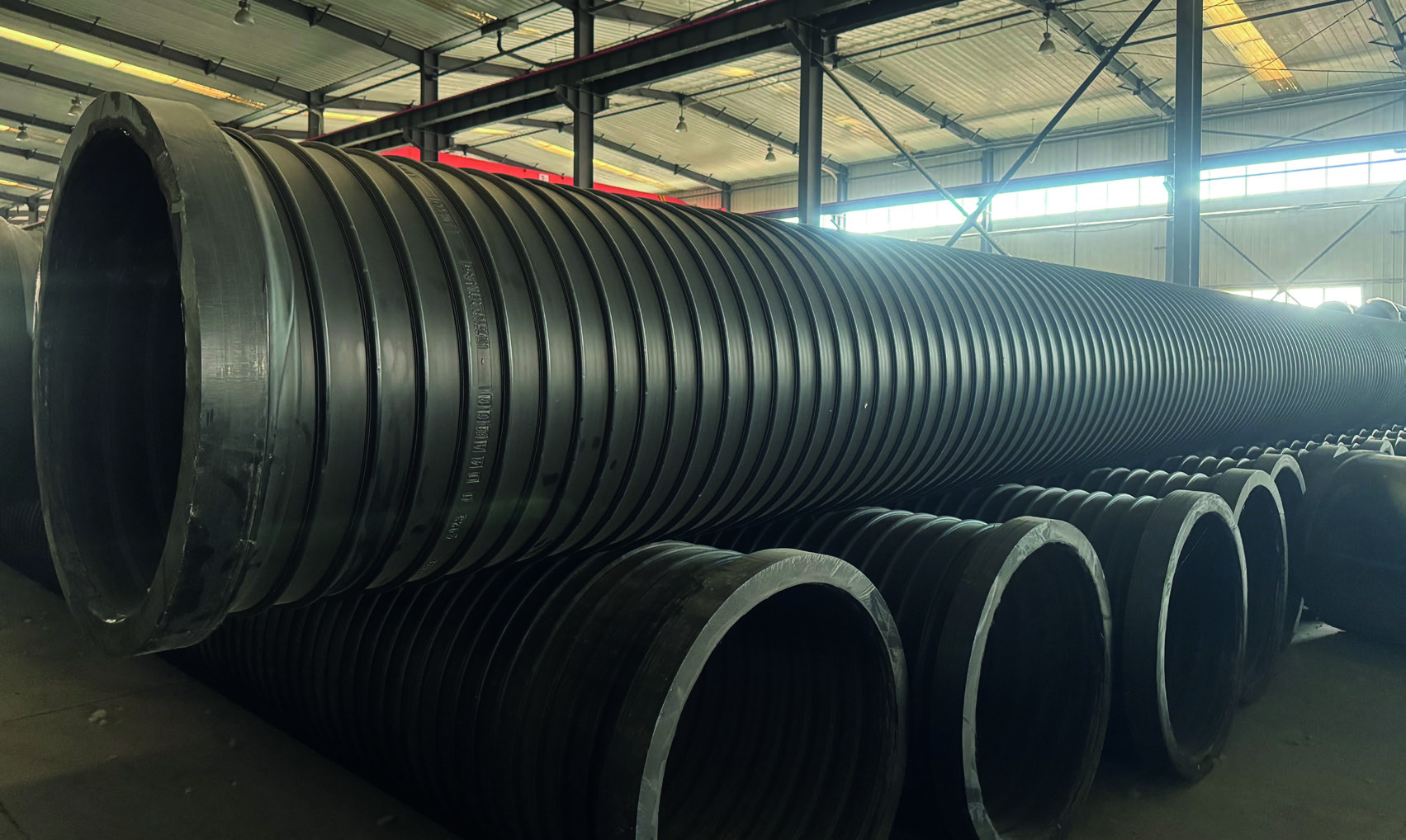
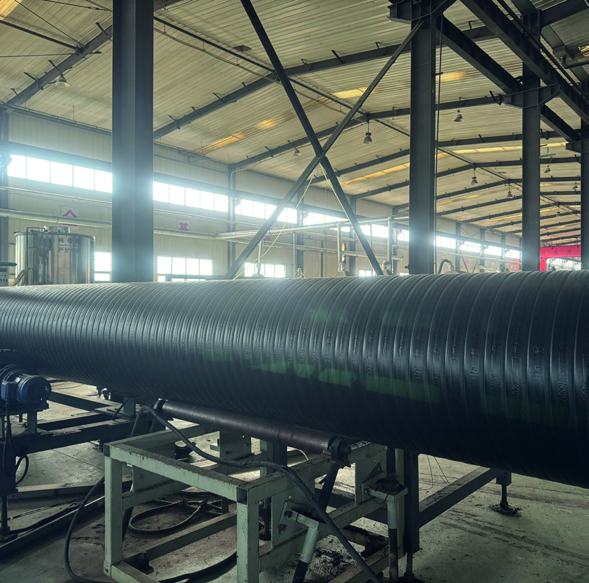
Large-diameter RPEP equipment on the factory floor, backed by incoming inspection records for every production batch.
10 / Digital-to-field workflow
Medium, flow, diameter, operating and design pressure, surge, route, standard and drawings.
Confirm reinforced composite pressure pipe is the correct product category.
Match diameter, pressure class, wall reference, fittings and connection method.
Agree required tests, documents, inspection points and acceptance criteria.
Coordinate production sequence, traceability, special fabrication and delivery.
Provide agreed jointing and field guidance without replacing the project designer.
11 / Project questions
It is reviewed for water transmission, regional transfer, irrigation, industrial water and other pressurized duties where the composite structure fits project requirements.
No. It uses a steel-wire-reinforced PE composite structure with separate sealing, protective and strengthening roles.
Available pressure classes and wall thicknesses vary by diameter. Use the matching row in the technical table for selection.
It is one published test case. It is not a universal rating for every diameter, wall configuration or project condition.
Water-supply PE composite pipe
Water-supply reinforced PE composite pipe is made by spiral winding steel-wire-reinforced PE strips, bonding adjacent strips and adding an outer PE protective layer. Additional composite PE and steel-wire reinforcement join neighbouring strips between them.
Download the English brochure (PDF) ↓ · Download centre →
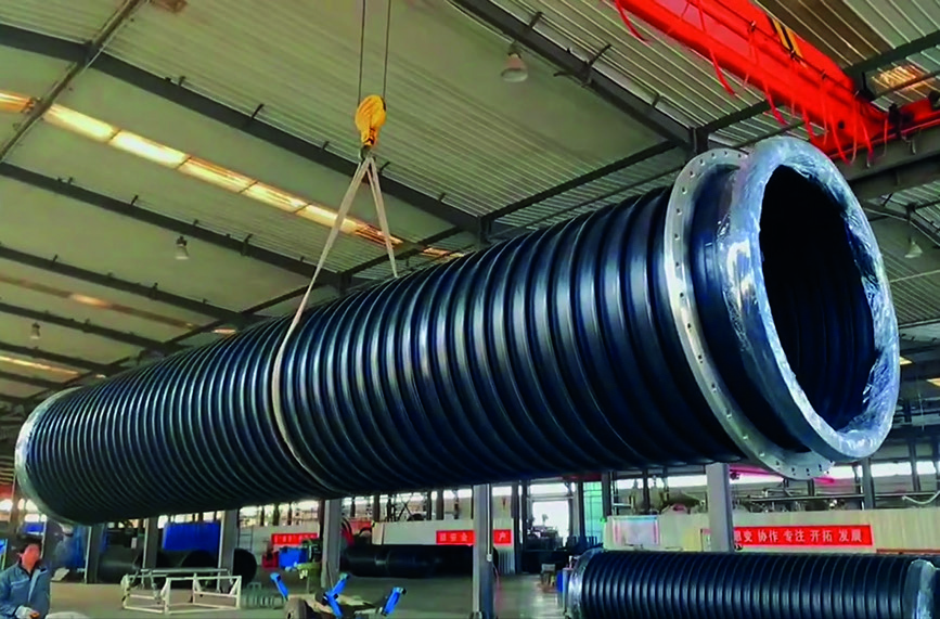
The steel-wire-reinforced strip, bonded seams and outer PE layer work together to form the composite pressure wall. The pipe is used for water transfer and other compatible media.
02 / Materials
Combines flexibility and bonding performance to form the flow passage and composite base.
High-strength wire reinforces the pipe wall, with tensile strength of approximately 2000 MPa.
Heat bonds adjacent strips and composite layers for adhesion, impact resistance and crack resistance.
04 / Product characteristics
 01
The PE wall combines corrosion resistance and flexibility, with interlayer peel strength above 400 N/cm.
 02
Steel wire is bonded with the PE base to reinforce the pressure wall. Check the diameter, wall and joint for each pressure class.
 03
PE encases the wire, while heat-bonded strips form an integrated composite wall.
 04
Spiral winding and heat bonding reduce the equipment rotation space needed for large-diameter production.
 05
Circumferential wire reinforcement retains longitudinal flexibility for route planning.
 06
Spiral winding supports large diameters, with sizes from DN50 to DN5000.
05 / Water-pipe jointing
Select the connection method to match diameter, pressure class and site conditions.
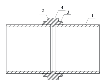
Both pipe ends are prefabricated with double-flat solid-wall profiles and thickened PE joint ends, then butt-fused on site with a PE butt-fusion machine. Callouts: 1 pipe; 2 PE joint end; 3 locating step; 4 weld bead.
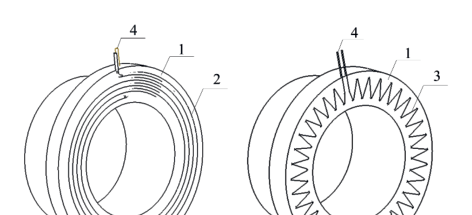
Resistance wires are embedded at even spacing in the PE joint end faces and energised on site to fuse the two faces; compact units allow multiple simultaneous welds. Callouts: 1 joint bead end face; 2 circular heating wire; 3 W-pattern heating wire; 4 power terminal.
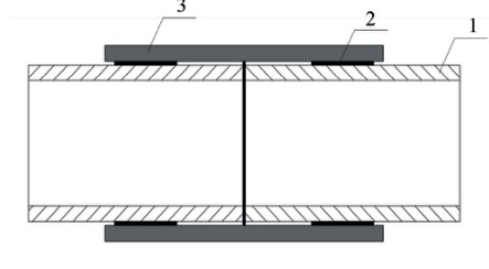
A PE sleeve with embedded heating wire receives the two prepared pipe ends; after electrofusion and cooling, the internal supports are removed. Callouts: 1 pipe; 2 fusion zone; 3 sleeve.
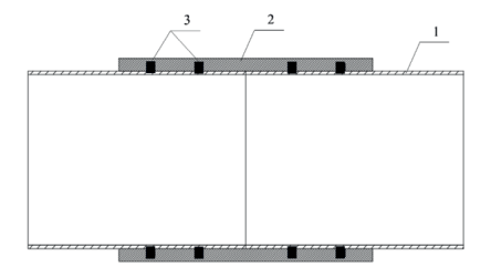
Two sealing rings seated between pipe and sleeve are compressed against the pipe outer wall and sleeve inner wall — simple to install with dual sealing. Callouts: 1 pipe; 2 electrofusion sleeve; 3 dual sealing rings.
06 / Applications
For drinking water, gas, oil and chemical duties, select the pipe and connection system to meet medium and local code requirements.
Standards
Product standard for reinforced PE composite pipe.
Related reference standards.
Related reference standard.
Projects
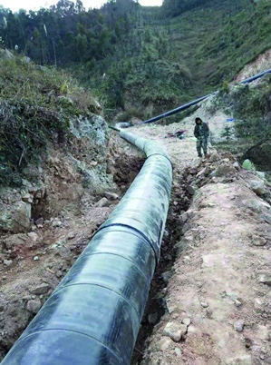
DN700 · 0.8 MPa · 12 km
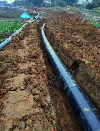
DN600 · 1.0/1.6 MPa · 25 km
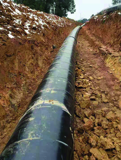
DN1000 · 1.25 MPa · 20 km
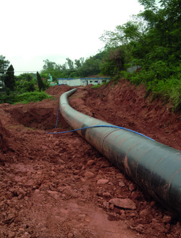
DN1000/DN600 · 1.0 MPa · 18 km
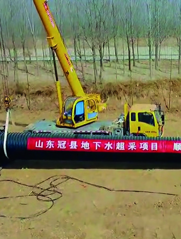
DN1400 · 1.0 MPa
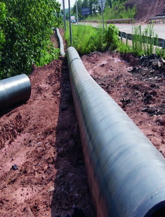
DN1000 · 1.6 MPa · 30 km
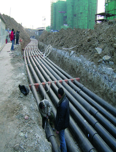
DN315/DN400 · 1.6 MPa · 80 km
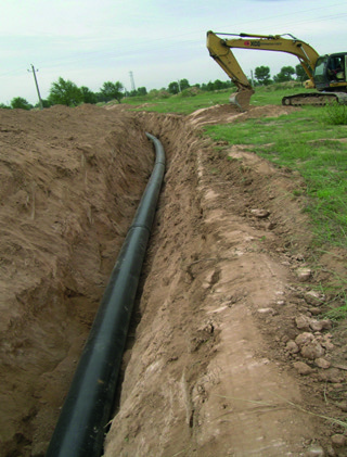
DN500 · 1.0 MPa · 40 km
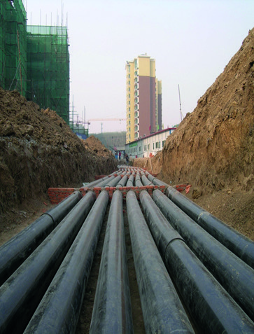
DN315 · 1.6 MPa · 50 km
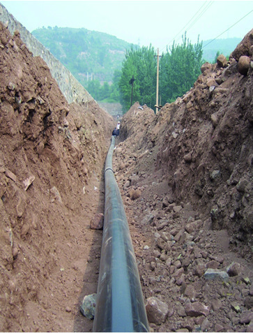
DN400 · 1.0 MPa · 60 km
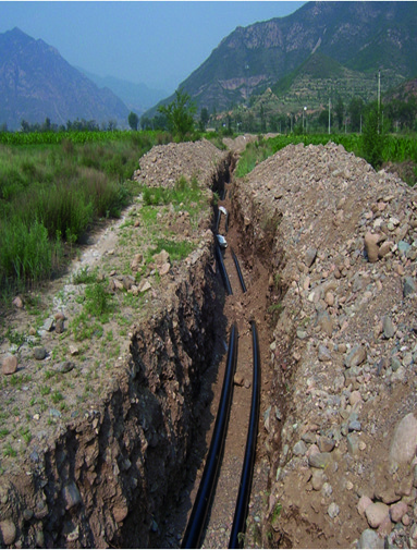
DN315 · 1.0 MPa · 30 km
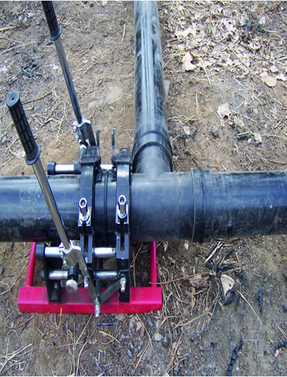
DN200 · 1.6 MPa · 20 km
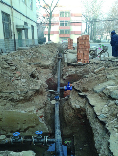
DN160 · 1.6 MPa · 15 km
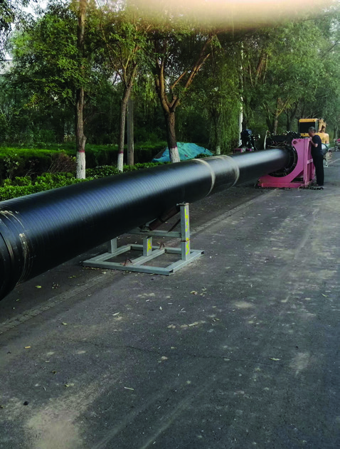
DN630 · 1.6 MPa · 5.5 km
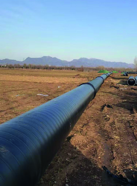
DN315–DN800 · 1.0/2.0 MPa · 20 km
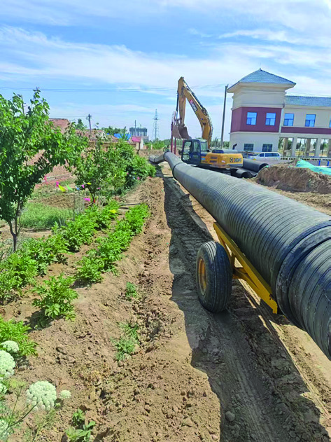
DN800/DN900 · 1.0/1.6 MPa · 43 km
07 / View the full DN50–DN5000 dimensions and wall table ↑More project case studies →
12 / Your pressure basis
We will identify the likely product path, missing design inputs and the next technical documents needed. Website data is not treated as final project approval.
PROJECT ENQUIRY
Application · medium · diameter · pressure or ring stiffness · quantity · destination